
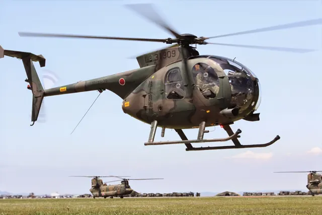
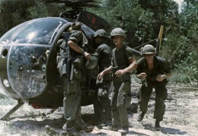
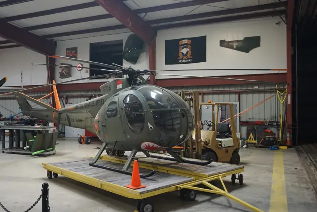
MD 500E
MD 500E: The selected cyclic resistance accompanies the exact rotor/control configuration.
Aircraft and simulator scope
- MD 500E · MSFS 2020 · Variant starting point
- MD 500E · MSFS 2024 · Variant starting point
- MD 500E · X-Plane 11 · Variant starting point
- MD 500E · X-Plane 12 · Variant starting point
MD 500E · The selected MD 500E is not covered by Taog's OH-6A/500C manual; rotor count and trim equipment cannot inherit exact review. The manual explicitly covers OH-6A and Hughes 500C. MD 500E is outside this document's variant scope.
The simulator model and controls
Hughes developed the compact, single-turbine OH-6 for the US Army's Light Observation Helicopter programme. Its reconnaissance and utility roles were followed by the civilian Hughes 500 lineage.
This starting point selects MD 500E. Its aircraft-level settings do not select a particular developer’s custom systems.
How this profile feels
The selected cyclic resistance accompanies the exact rotor/control configuration. Spring resistance builds with the selected airspeed response. A separate aerodynamic term adds speed-dependent control load. Cyclic damping adds resistance to hardware motion.
Electric trim and SAS release remain separate from a hardware spring latch. Local force trim holds the selected hardware centre. Autopilot following is off.
Controls and trim
Hughes/MD 500 variants use different rotor and equipment fits. The reviewed 500E has five main blades; the MSFS 2024 OH-6 package describes four blades, adjustable friction and electric cyclic trim without hydraulic boost. SAS and trim-release functions are implementation-specific.
About the values
The gains are normalized profile settings. They describe the chosen effect balance; hand force depends on the device and its output limits. IAS references are tuning values rather than operating limits. Physical acceptance of this revision remains pending.
Documentary review and sources
These decisions describe the documentary basis and remaining gaps for this revision. Aircraft documentation and a starting setting describe different kinds of evidence.
Aircraft and variant
Not yet reviewedThis starting point selects MD 500E. Its aircraft-level settings do not select a particular developer’s custom systems.
Flight controls
Not yet reviewedHughes/MD 500 variants use different rotor and equipment fits. The reviewed 500E has five main blades; the MSFS 2024 OH-6 package describes four blades, adjustable friction and electric cyclic trim without hydraulic boost. SAS and trim-release functions are implementation-specific.
Trim
Not yet reviewedElectric trim and SAS release remain separate from a hardware spring latch. Local force trim holds the selected hardware centre. Autopilot following is off.
Autopilot and stability
Not yet reviewedAutopilot following is off; the configured spring and load retain the hardware feel.
Equipment
Not yet reviewedGear, flap and ground cues follow the selected settings and available simulator-reported states.
Speeds and limits
Not yet reviewedThe indicated-speed references set the profile response scale; they are separate from aircraft operating limits.
Simulator integration
Not yet reviewedThe profile targets msfs2020, msfs2024, xplane11, xplane12. Add-on-specific controls use only the supported references configured by this profile.
Force-feedback settings
Not yet reviewedThe settings define the profile’s effect balance. Device output limits affect physical hand force.
Starting settings and their rationale
These configured values are starting estimates. The explanations describe what each setting controls; physical validation appears separately below.
| Setting | Starting value | What it controls and why |
|---|---|---|
| Spring strength | Starting value0 | What it controls and whyThe selected cyclic resistance accompanies the exact rotor/control configuration. The baseline spring is 0. Its low-speed blend reaches baseline strength at 55 KIAS. |
| Master force gain | Starting value0.85 | What it controls and whyScales overall profile strength while preserving effect balance, subject to device and output limits. |
| Profile force gain | Starting value0.35 | What it controls and whyThe aerodynamic-load gain is 0.35 with an indicated-speed reference of 110 KIAS. This supplies speed-dependent loading alongside the spring. |
| Force tuning speed/reference | Starting value110.0 kt | What it controls and whySets the IAS reference for aerodynamic loading. It is an estimate, not published cruise TAS or a flight limit. |
| Spring response reference speed | Starting value55.0 kt | What it controls and whySets the IAS where the low-speed blend reaches baseline strength; high-speed stiffening also uses it. |
| Aileron force scale | Starting value1 | What it controls and whyRoll and pitch aerodynamic scales are 1 and 1, respectively. They set the aerodynamic axis balance. No custom spring-travel curve is enabled. |
| Elevator force scale | Starting value1 | What it controls and whyScales pitch aerodynamic loading; pitch spring travel and trim responses are separate settings. |
| Trim feel | Starting valueDisabled | What it controls and whyRetained for compatibility and group membership. Trim relief, rather than this flag, controls centre movement. |
| Trim relief | Starting valueDisabled | What it controls and whyAllows trim relief with supported control law and valid telemetry. Axis authorities set its amount. |
| Autopilot follow | Starting valueDisabled | What it controls and whyAutopilot following is off; the configured spring and load retain the hardware feel. |
| Autopilot neutral hold | Starting valueDisabled | What it controls and whyPermits centering hold during a supported AP state, separate from following a moving target. |
| Output force limit | Starting value0.55 | What it controls and whyCaps directed-force output. Native spring effects and device limits remain separate. |
All 44 starting settings and their rationale
The settings define the profile’s effect balance. Device output limits affect physical hand force.
| Setting | Starting value | What it controls and why |
|---|---|---|
| Spring strength | Starting value0 | What it controls and whyThe selected cyclic resistance accompanies the exact rotor/control configuration. The baseline spring is 0. Its low-speed blend reaches baseline strength at 55 KIAS. |
| Spring deadband | Starting value0.02 | What it controls and whySets travel around the centre before the baseline spring resists. Smaller values engage it sooner. |
| Profile force gain | Starting value0.35 | What it controls and whyThe aerodynamic-load gain is 0.35 with an indicated-speed reference of 110 KIAS. This supplies speed-dependent loading alongside the spring. |
| Master force gain | Starting value0.85 | What it controls and whyScales overall profile strength while preserving effect balance, subject to device and output limits. |
| QBlend Enabled | Starting valueEnabled | What it controls and whyAllows baseline spring strength to rise with indicated airspeed where the control law permits it. |
| QSpring Minimum Factor | Starting value1 | What it controls and whySets low-speed spring strength as a fraction of baseline when blending is enabled. One keeps full strength. |
| QSpring Start Knots | Starting value15.4 kt | What it controls and whySets the IAS where the low-speed spring blend starts rising. This is a feel threshold, not a flight limit. |
| Spring response reference speed | Starting value55.0 kt | What it controls and whySets the IAS where the low-speed blend reaches baseline strength; high-speed stiffening also uses it. |
| Force tuning speed/reference | Starting value110.0 kt | What it controls and whySets the IAS reference for aerodynamic loading. It is an estimate, not published cruise TAS or a flight limit. |
| Airspeed spring stiffening gain | Starting value0 | What it controls and whyAdds permitted spring resistance above the full-blend speed. Zero removes this high-speed increase. |
| Airspeed spring stiffening limit | Starting value5 | What it controls and whyLimits the squared airspeed ratio used for high-speed spring stiffening; it is not a device-force cap. |
| Aileron force scale | Starting value1 | What it controls and whyRoll and pitch aerodynamic scales are 1 and 1, respectively. They set the aerodynamic axis balance. No custom spring-travel curve is enabled. |
| Elevator force scale | Starting value1 | What it controls and whyScales pitch aerodynamic loading; pitch spring travel and trim responses are separate settings. |
| Output force limit | Starting value0.55 | What it controls and whyCaps directed-force output. Native spring effects and device limits remain separate. |
| Trim feel | Starting valueDisabled | What it controls and whyRetained for compatibility and group membership. Trim relief, rather than this flag, controls centre movement. |
| Trim relief | Starting valueDisabled | What it controls and whyAllows trim relief with supported control law and valid telemetry. Axis authorities set its amount. |
| Elevator Authority | Starting value0.3 | What it controls and whyScales supported pitch-trim relief and permitted centre movement. Zero removes pitch response. |
| Aileron Authority | Starting value0.3 | What it controls and whyScales supported roll-trim relief and permitted centre movement. Zero removes roll response. |
| Force Trim Enabled | Starting valueEnabled | What it controls and whyElectric trim and SAS release remain separate from a hardware spring latch. Local force trim is on. It holds a selected spring centre with strength 0.55. |
| GLoad Enabled | Starting valueDisabled | What it controls and whyAllows load-factor changes to modify permitted spring laws. Passive fly-by-wire feel can suppress it. |
| Rate Damping Enabled | Starting valueEnabled | What it controls and whyEnables rate damping with the configured coefficients and control law. |
| Autopilot follow | Starting valueDisabled | What it controls and whyAutopilot following is off; the configured spring and load retain the hardware feel. |
| Autopilot follow authority | Starting value0.05 | What it controls and whySets admitted AP-follow gain, not a percentage of travel. Runtime ownership and input limits still apply. |
| Autopilot neutral hold | Starting valueDisabled | What it controls and whyPermits centering hold during a supported AP state, separate from following a moving target. |
| Autopilot neutral hold strength | Starting value0.6 | What it controls and whySets admitted AP neutral-hold strength; inactive while neutral hold is disabled. |
| Enabled | Starting valueEnabled | What it controls and whyEnables aerodynamic cues; each still needs nonzero strength and its simulator conditions. |
| Gain | Starting value0 | What it controls and whySets stall-buffet strength. Zero removes the cue without changing simulator stalls or warnings. |
| Gain | Starting value0 | What it controls and whySets high-Mach buffet strength; onset and full-strength thresholds are separate. |
| Gain | Starting value0 | What it controls and whySets flap buffet at the configured position and speed gates. Flap movement texture is separate. |
| Maximum flap index | Starting value1 | What it controls and whySets the final flap index for detent normalization. UP plus three detents uses maximum index3. |
| Minimum flap index | Starting value1 | What it controls and whySets the first flap detent that admits buffet; this is a handle index, not degrees. |
| Gain | Starting value0 | What it controls and whySets gear aerodynamic buffet; movement and ground-contact cues are separate. |
| Shaker Enabled | Starting valueDisabled | What it controls and whyPermits shaker at supported warning conditions; the switch does not establish aircraft equipment. |
| Stick shaker amplitude | Starting value0.5 | What it controls and whySets triggered shaker strength; inactive while the shaker feature is disabled. |
| Enabled | Starting valueEnabled | What it controls and whyEnables ground effects; each still needs its own strength and contact or motion telemetry. |
| Gain | Starting value0 | What it controls and whySets rolling texture strength, modified by speed, surface and undercarriage configuration. |
| Gain | Starting value0 | What it controls and whySets gear-bump texture during ground motion, separate from touchdown impact. |
| Gain | Starting value0.5 | What it controls and whySets landing-impact strength; landing telemetry and response shape determine the pulse. |
| Gain | Starting value0 | What it controls and whySets reverse-thrust vibration with valid reverser and engine conditions. Zero removes the cue. |
| Enabled | Starting valueEnabled | What it controls and whyEnables engine cues with nonzero settings and valid running-engine telemetry. |
| Gain | Starting value0.06 | What it controls and whySets estimated engine vibration using configured telemetry and response, not measured cockpit vibration. |
| Enabled | Starting valueEnabled | What it controls and whyEnables accessory cues with configured strengths and observed accessory movement. |
| Gain | Starting value0 | What it controls and whySets texture from observed flap movement; a command without movement does not establish the cue. |
| Gain | Starting value0 | What it controls and whySets texture from observed gear movement, separate from aerodynamic and touchdown effects. |
Limits and open questions
- The selected MD 500E is not covered by Taog's OH-6A/500C manual; rotor count and trim equipment cannot inherit exact review. The manual explicitly covers OH-6A and Hughes 500C. MD 500E is outside this document's variant scope.
- The selected MD 500E is not covered by Taog's OH-6A/500C manual; rotor count and trim equipment cannot inherit exact review. Adjustable cyclic and collective friction and low stick forces are described; hydraulic boost is stated to be unnecessary.
- The selected MD 500E is not covered by Taog's OH-6A/500C manual; rotor count and trim equipment cannot inherit exact review. Electrical cyclic trim actuators remove flight loads, but the simulator circuit-breaker and checklist descriptions explicitly mark them not simulated. A generic force-trim hold is not established by this source.
- The selected MD 500E is not covered by Taog's OH-6A/500C manual; rotor count and trim equipment cannot inherit exact review. Automatic re-ignition and engine governor functions are not automatic-flight equipment; no applicable autopilot is documented.
- The selected MD 500E is not covered by Taog's OH-6A/500C manual; rotor count and trim equipment cannot inherit exact review. The OH-6A/500C have a fully articulated four-blade main rotor, two-blade tail rotor, fixed skids and different Allison engine installations. MD 500E rotor settings cannot inherit this evidence.
- The selected MD 500E is not covered by Taog's OH-6A/500C manual; rotor count and trim equipment cannot inherit exact review. Approximate cruise is 110 knots for OH-6A and 125 knots for 500C, without a clear IAS basis in the overview. A common 110-knot reference is an estimate for the latter.
- The selected MD 500E is not covered by Taog's OH-6A/500C manual; rotor count and trim equipment cannot inherit exact review. The manual publishes simulator control assignments and identifies non-simulated cyclic trim. It does not verify the retained force-trim implementation or correct external reference direction.
- The selected MD 500E is not covered by Taog's OH-6A/500C manual; rotor count and trim equipment cannot inherit exact review. Low cyclic forces and equal fore/aft force after longitudinal trimming are qualitatively documented. No calibrated device-force curve is supplied.
- MD 500E documentary evidence does not establish force-feedback hardware acceptance.
Physical validation
No physical force validation is recorded in this public catalogue for this revision. Documentary review and software checks do not establish how a particular device feels.